
TM 10-3990-205-12&P
1-10 LOCATION AND DESCRIPTION OF SPREADER C O M P O N E N T S
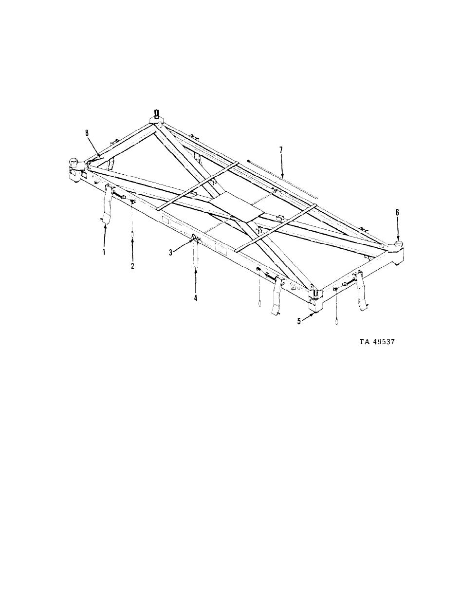
Figure 1-2. Location of Major Components
ALIGNMENT ARM (1). When in the down position, assists the hoisting equipment operator
in positioning the spreader on the freight container.
ALIGNMENT ARM RELEASE CABLE (2). Pulling the cable pulls the spring pin out of
the alignment arm allowing the alignment arm to be moved to either the up or down posi-
tion.
TWIST LOCK ACTUATING CAM (3). Rotates in either direction, exerting a force on
the control rods to move the four twist locks to the locked or unlocked position.
TWIST LOCK CAM ACTUATING CABLE (4). Pulling the cable in one direction rotates
the four twist locks to the locked position. Pulling the cable in the opposite direction
rotates the four twist locks to the unlocked position.
TWIST LOCK COUPLER (5). The spreader is equipped with a twist lock at each of the
four corners. When the twist locks are parallel to the side members of the spreader frame
they are in the unlocked position. When the spreader is in position on a freight container.
1-4
