
TM 10-3990-205-12&P
3-8 REPLACEMENT OF ALIGNMENT ARM AND COMPONENTS - CONT
- CONT
The spring (7) is under pressure. Be aware and
exercise care while performing the following pro-
cedure. Wear eye protection during removal of
spring.
Remove the nuts (8), lockwashers (9), capscrews (10), and bracket (11).
e.
Remove the spring (7) from the spring pin assembly (12).
f.
Remove the nut (13), lockwasher (14), and remove the eyebolt (15) from
g.
the bracket (16).
Remove the screw (17) and rubber bumper (18).
h.
Remove the nut (19), capscrew (20), and nut (21).
i.
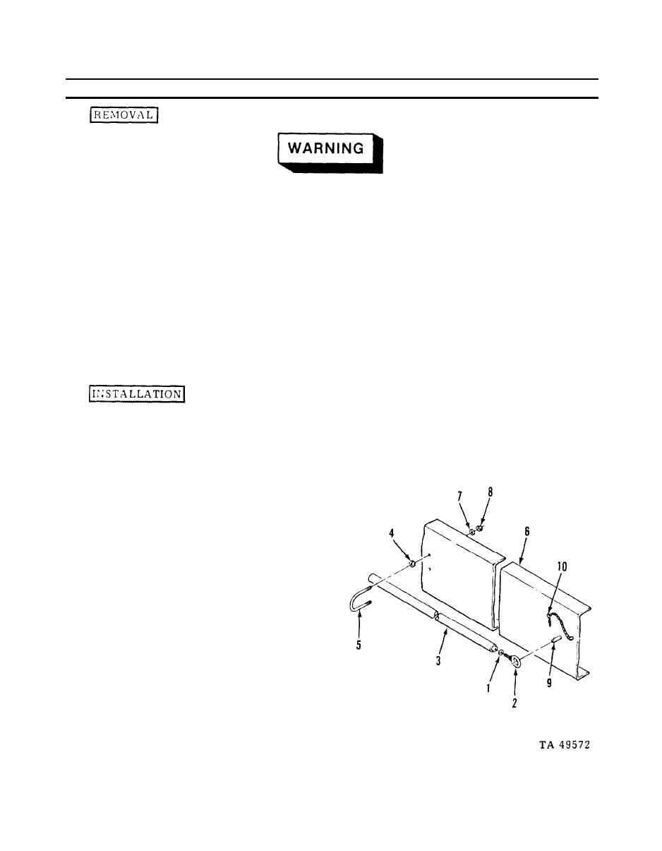
ALIGNMENT ARM POSITIONING ROD
1.
Place the lockwasher (1)
a.
on the eyebolt (2), and
screw the eyebolt (2) into
the rod (3).
Install the nuts (4) on the
b.
U-bolt (5), and insert the
ends
of
the
U-bolt
(5)
through the holes in the
spreader frame (6). Install
the lockwashers (7) and
nuts (8) on the U-bolt (5).
Tighten
the
nuts
(4)
against the frame (6) to
secure the U-bolt (5).
Slide the alignment arm
c.
positioning rod (3) through
the U-bolt (5). Place the
eyebolt (2) on the mount-
ing pin (9) and install the
hairpin (10).
3-17
