
TM 10-3990-205-12&P
3-3 REPLACEMENT OF TWIST LOCK ASSEMBLY COMPONENTS - CONT
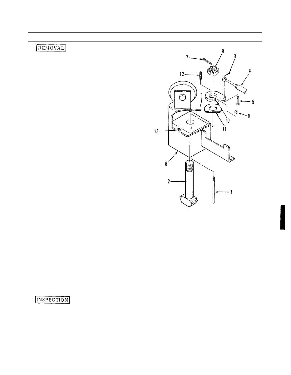
Push the cam locking rod
1.
(1) up, and pull the twist
locking cam actuating
cable to move the twist
locks
(2)
to
the
unlocked
position.
Remove and discard the cotter
2.
pin (3), and lift the control
rod
(4)
off
the
clevis
pin
15).
3.
Hold the cam locking rod
(1)
in
the
raised
position,
and rotate the twist lock
(2) to a position for easiest
access to the components
inside the twist lock housing
(6).
4.
Remove and discard the cotter
pin (7). and remove the castel-
lated nut (8).
5.
Hold the cam locking rod
(1) in a raised position
and remove the nut (9).
Remove the cam locking
TA 49562
rod (1).
6.
Pry lightly on the bayonet end of the twist lock (2) on one side, and then
the other, until the twist lock (2) has moved upward enough to insert a 1/2-inch
wood or metal spacer between the cam (10) and washer (11).
7.
Punch out and remove the key (12).
Remove the twist lock (2), cam (10), and washer (11).
8.
NOTE
Do not remove the grease fitting (13) unless replacement
is necessary.
Inspect the twist lock (2) for damage and excessive wear.
1.
3-5
