TM 10-3990-205-12&P
3-3 REPLACEMENT OF TWIST LOCK ASSEMBLY COMPONENTS - CONT
- CONT
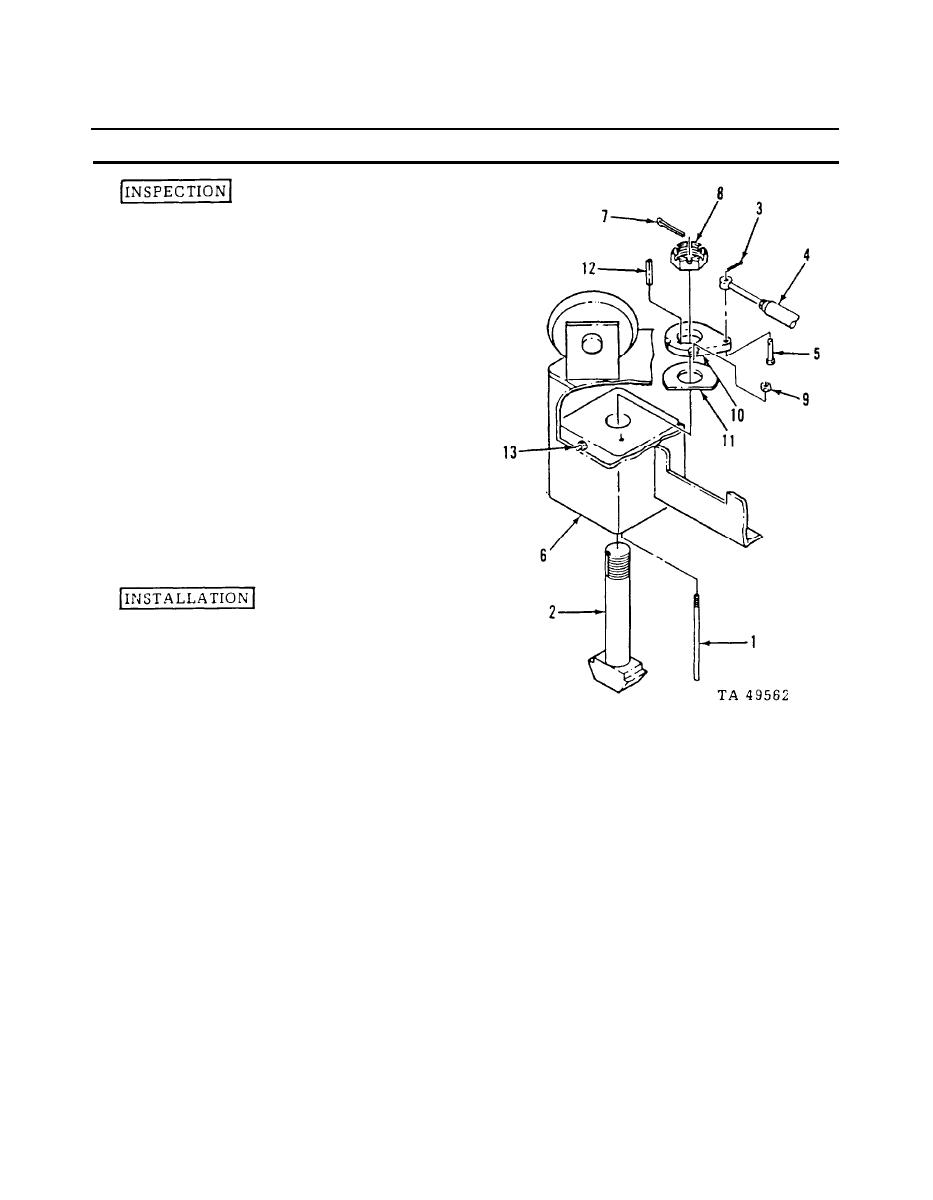
Inspect the threads on
2.
all threaded pars and
replace any parts that
have defective threads.
Inspect the cam (10) for damage
3.
or excessive wear.
Check all remaining parts
4.
for serviceable condition.
5.
If the grease fitting (13)
was not removed, use a grease
gun filled with grease, MIL-G-
10924, and apply grease to
the
grease
fitting
(13).
to
make sure that the grease
passage
in
the
twist
lock
housing (6) is clear.
Insert the twist lock (2) into
1.
the twist lock housing (6)
and install the key (12), and
flat washer (11).
With the notches in the locking cam (10) facing upward, insert the clevis pin
2.
(5) through the locking cam (10) from the bottom. Install the locking cam (10)
and clevis pin (5) in position on the twist lock (2).
Install the castellated nut (8) and a new cotter pin (7).
3.
Install the cam locking rod (1) and nut (9).
4.
Position the control rod (4) on the clevis pin (5) and install a new cotter pin (3).
5.
NOTE
Only one of the four twist lock asemblies is equipped with
a locking cam (10), cam locking rod (1), and nut (9). If mainte-
nance is being performed on one of the twist locks without
a locking cam, the cam locking rod (1) will still have to be
raised in order to rotate the twist locks.
3-6

