TM 5-3895-367-14&P
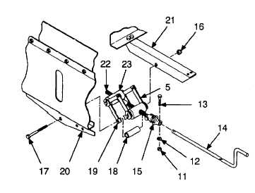
5-2. COUPLER HITCH AND CRANK REPAIR (CONT).
(2)
Position the assembled pantograph links (5
and 19), screw (22), and nut housings (23)
for installation on coupler support bracket
(20) and coupler angle (21).
NOTE
Upper pantograph links have large
hole. Lower pantograph links have
small hole.
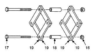
(3)
Assemble lower pantograph links (19) as
shown, then install bolt (17) and spacer (18).
NOTE
Do not overtighten locknut.
Pantograph links must be free to open
and close.
(4)
Secure bolt (17) using new locknut (16).
(5)
Install hitch adjusting crank (14) through side
of spreader.
(6)
Install hitch adjusting crank (14) on universal
joint (15) using screw (13), new lockwasher
(12), and nut (11).
WARNING
Bar assembly will be unsupported until
mounting hardware is installed. Use
assistance when Installing bar
assembly. Failure to follow this
warning could cause injury.
(7)
Install bar assembly (4), two spacer guides
(10), and two spacer plates (9) on spreader
using 10 screws (8), new lockwashers (7),
and nuts (6). Tighten bar assembly
mounting screws to 60 lb-ft.
(8)
Assemble upper pantograph links (5) as
shown, then install bolt (3) and spacer (2).
5-6