TM 5-3895-367-14&P
(5)
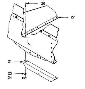
Remove four nuts (24), lockwashers (25),
and screws (26) securing coupler angle (21)
to bearing support brackets (27). Remove
coupler angle. Discard lockwashers.
b. Disassembly.
(1)
Remove nut (28), lockwasher (29), and
screw (30) securing universal joint (15) to
adjusting screw (22). Remove universal
joint. Discard lockwasher.
(2)
Remove lubrication fitting (31) from
universal joint (15).
(3)
Remove two cotter pins (32) and flatwashers
(33) from each nut housing (23). Remove
upper pantograph links (5) and lower
pantograph links (19) from nut housings.
Discard cotter pins.
NOTE
Nut housings are tapped for left-hand
and right-hand threads. Tag nut
housings before removing from
adjusting screw.
(4)
Unscrew and remove two nut housings (23)
from adjusting screw (22).
(5)
Remove screw (34) and lockwasher (35)
securing each latch (36) to latch lever (37).
Discard lockwashers.
(6)
Remove latch lever (37) from two housings
(38). Latches (36) will come out as latch
lever is removed.
(7)
Remove four nuts (39), lockwashers (40),
and bolts (41) securing each housing (38) to
bar assembly (4). Remove housings from
bar assembly. Discard lockwashers.
(8)
Remove two cotter pins (42) from each shaft
(43). Remove shaft, dog (44), and spring
(45) from each housing (38). Discard cotter
pins.
5-3