TM 5-3895-367-14&P
(4)
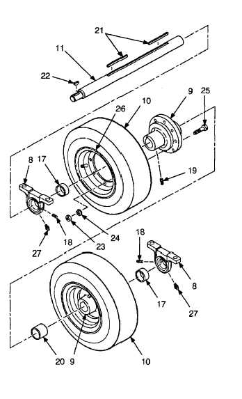
Install key (21) in shaft (11). Tap shaft
through one hub (9). Ensure that valve stem
(28) on tire (10) faces outside.
(5)
Slide spacer (20) onto shaft (11), then install
second key (21).
(6)
Tap shaft (11) through remaining hub (9).
Ensure that valve stem on tire (10) faces
outside.
(7)
If necessary, install two setscrews (18) in
each bearing (8).
(8)
Slide spacer (17) and bearing (8) on each
side of shaft (11).
(9)
Install woodruff key (22) in shaft (11).
d.
Assembly.
e.
Installation.
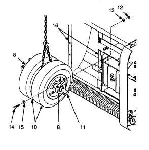
(1) Install lubrication fitting (27) in each bearing
(1)
Wrap a lifting sling or chain around shaft (11)
(8).
in between tires (10).
(2)
Using a suitable lifting device, raise shaft (11)
(2) Install hub (9) on rims (26) using eight screws
and tires (10) and position for installation.
(25), new lockwashers (24), and nuts (23).
Hub must be installed from side of tire
(3)
Secure each bearing (8) to bearing supports
opposite valve stem (28) with lip (29) facing
(16) using two screws (14), flatwashers (15),
valve stem. Tighten hub mounting nuts to 39
new lockwashers (13), and nuts (12).Tighten
Ib-ft.
bearing mounting screws to 60 lb-ft.
(3) Inflate tires (10) to 65 psi.
4-69